
YOUR CONFIGURATION
RCM-H-1C-10X
- SKU
- 260021
- HS code
- 8536 49 00 99
- Supply
- 85–250 VAC
- Relay rating
- 10 A
- Relays
- 1
- Current measurement
- Not included
Switch connected equipment with the supply and relay rating your installation needs.
From relay control to analog, digital and serial connections.
Find the connections your installation needs. Explore 12 RCM relay configurations, eight CMD input/output configurations and two CMD serial-interface models.
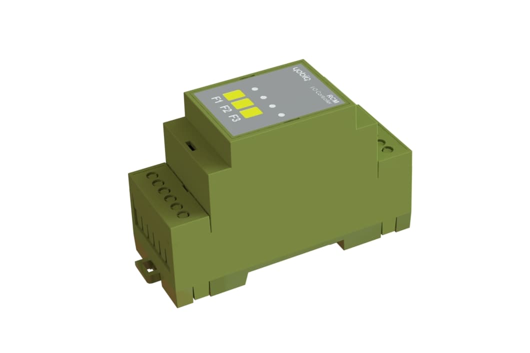 YOBIIQ / RCM · enclosure
Start with what you need to connect. Compare supply voltage, relay rating and current measurement, then choose your model.
Choosing a relay? Check the load type and starting current as well as the relay rating. We can help match the module to your installation.
Switch connected equipment with the supply and relay rating your installation needs.
| Model | SKU | Interface | Supply | Relay rating | Current measurement |
|---|---|---|---|---|---|
| 260021 | 1 relay output | 85–250 VAC | 10 A | Not included | |
| 260022 | 2 relay outputs | 85–250 VAC | 10 A | Not included | |
| 260023 | 2 relay outputs | 85–250 VAC | 10 A | Included | |
| 260024 | 1 relay output | 85–250 VAC | 16 A | Not included | |
| 260025 | 2 relay outputs | 85–250 VAC | 16 A | Not included | |
| 260026 | 2 relay outputs | 85–250 VAC | 16 A | Included | |
| 260027 | 1 relay output | 5–24 VDC | 10 A | Not included | |
| 260028 | 2 relay outputs | 5–24 VDC | 10 A | Included | |
| 260029 | 2 relay outputs | 5–24 VDC | 10 A | Included | |
| 260030 | 1 relay output | 5–24 VDC | 16 A | Not included | |
| 260031 | 2 relay outputs | 5–24 VDC | 16 A | Included | |
| 260032 | 2 relay outputs | 5–24 VDC | 16 A | Included | |
| 260033 | 1 DI · 1 AI · 1 DO · 1 AO (0–10 V) | 5–24 VDC | — | — | |
| 260034 | 1 DI · 1 AI · 1 DO · 1 AO (4–20 mA) | 5–24 VDC | — | — | |
| 260035 | 2 AI · 2 AO (0–10 V) | 5–24 VDC | — | — | |
| 260036 | 2 AI · 2 AO (4–20 mA) | 5–24 VDC | — | — | |
| 260037 | 2 DI · 2 DO | 5–24 VDC | — | — | |
| 260038 | 4 DI | 5–24 VDC | — | — | |
| 260039 | 4 AI | 5–24 VDC | — | — | |
| 260040 | 2 DI · 2 AI | 5–24 VDC | — | — | |
| 260041 | RS485 / RS232 | 85–250 VAC | — | — | |
| 260042 | RS485 / RS232 | 5–24 VDC | — | — |
DI = digital input; DO = digital output; AI = analog input; AO = analog output. Analog input ranges and digital channel ratings are available on request. A dash means that a specification does not apply to this comparison.
The guide below covers relay applications. For analog, digital I/O and serial projects, ask us for the documentation for your selected model.
Start with the equipment and the reason to control it. The relay, electrical design and application work together to make that action useful.
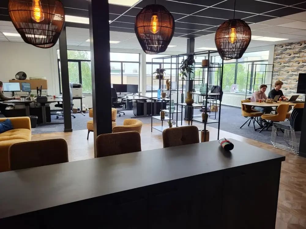
Shared-area lighting can remain on after a building closes, while occasional late use still needs to be accommodated.
Store the opening-hours schedule inside the RCM to switch a suitable lighting circuit. Staff can also control the equipment locally using the pushbuttons on the device.
A repeatable routine that the team can inspect and adjust as building use changes.

Ventilation equipment may run on a fixed routine even when room usage changes during the day.
Combine a suitable ventilation control circuit with room information in your application. The application decides when to send a command; the relay provides the switching interface. Keep the equipment’s own protective controls in place.
Connect the operating decision to the needs of the space and retain a record of requested changes.
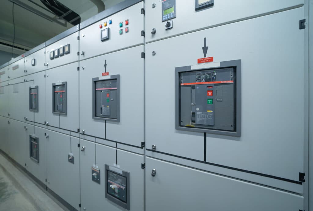
A routine switching task can mean travelling to another part of a site simply to reach a cabinet.
Design a remote control path for a suitable pump control circuit or contactor. Confirm the load and starting characteristics, then expose the supported action and state in the operations platform.
Handle suitable routine actions remotely, with the site’s electrical and operating requirements built into the design.
Explore how this device fits into a connected environment.
Bring remote switching to equipment that already exists. Connect suitable circuits to a LoRaWAN relay module and give your facilities team a way to request a change, review the reported state and keep an operating record in one application.
Your device communicates over LoRaWAN. A gateway forwards its messages to a network server, ready for your application to use.
Bring equipment status and remote control into your application. Explore the device’s supported functions below to plan your integration.
The RCM series supports remote switching, schedules stored inside the device and local control using its pushbuttons. A configurable fallback state defines the return state after power or network loss.
An authorised user requests an on/off change through the application. The integration sends the appropriate LoRaWAN downlink to the device and processes the reported status.
Switch a suitable circuit during a planned operating change.
The operating schedule is stored inside the RCM. Use it for planned switching, such as the opening-hours routine for shared-area lighting.
Apply a building’s agreed opening-hours routine to shared-area lighting.
Rules in the application can combine sensor or meter information with a switching request. Specify the rule, equipment constraints and expected response before enabling automatic control.
Use room measurements to inform a compatible ventilation control circuit.
Connect the device to a LoRaWAN network, then bring its data into the application your team uses. Each layer has a different job.
Connect devices and route their LoRaWAN messages.
Match the radio region, device profile and RCM payload decoder to the supplied model and firmware.
Plan your integrationGroup equipment by building, review device status and bring the information your team needs into one workspace. Shown: Yobiiq’s published device-management example; your dashboard is configured for the project.
Explore the platform example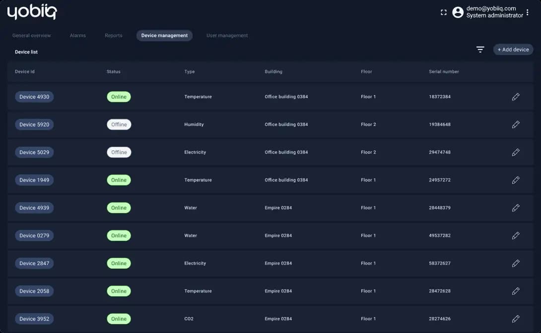
A practical overview to help you specify the right device and the system around it.
Product documentation| Function | Remote on/off switching of suitable equipment circuits |
|---|---|
| Installation format | DIN-rail mounting in an electrical enclosure |
| Connections | Screw-terminal wiring |
| Load selection | Match the relay rating, load type and switching duty to the selected hardware version |
| Network | LoRaWAN® |
|---|---|
| Command path | Application → network server → gateway → relay |
| Monitoring | Reported device status and switching events |
| Scheduling — RCM | Operating schedule stored inside the RCM |
| Local control — RCM | Equipment control using pushbuttons on the device |
| Fallback state — RCM | Configurable return state after power or network loss |
| Sensor-informed rules | Configured in the connected application |
Share the supply voltage, load type, running and starting current, channel count and preferred behaviour after a power or network interruption. These determine the correct relay or contactor arrangement.
Four things to settle before the first device goes into service.
Identify the equipment, electrical ratings and required switching frequency. Check whether a contactor or another interface is needed.
Confirm enclosure space, terminals and power requirements with the installer using the selected model’s documentation.
Register the device on the LoRaWAN network and configure payload handling and permissions in the application.
Verify switching, reported state, local operating procedures and the agreed behaviour after a loss of power or communication.
Practical answers about Relay & I/O modules.
Ask us something elseNo single relay rating covers every load. The installer must check the selected model’s limits against the load type, inrush current and switching duty. Some equipment needs an appropriately rated contactor or a dedicated control interface.
Yes. The schedule is stored inside the RCM itself and used for scheduled switching.
Yes, compatible devices can use the same LoRaWAN infrastructure. Your application still needs to understand each device’s data and commands. Combining them in a dashboard or automation rule is an application integration task.
A relay state describes the switching output. Confirming that a pump is moving water or that a fan is running may require separate feedback, such as a suitable meter or sensor. Design that confirmation into the application when it matters.
The RCM series returns to a configurable fallback state after power or network loss. Set this state to suit the connected equipment and the installation’s operating requirements.
Yes. The equipment can be controlled locally using the pushbuttons on the RCM device.
Tell us what you want to connect, monitor or control. We’ll help you find a starting point.
Talk to the team