INSTALLATION & OPERATION
RCMUser guide
Identify your RCM variant, plan its installation and understand remote switching, onboard schedules, local pushbuttons and configurable fallback behaviour.
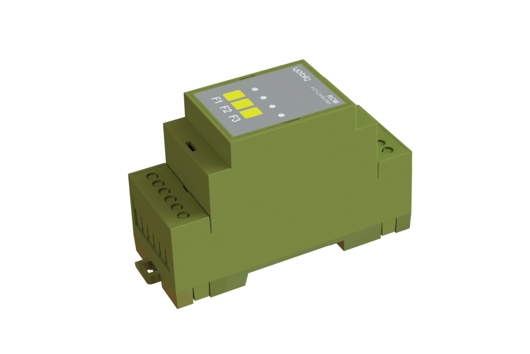
- 01 / Identify
- Identify your variant and Install it
- 02 / Connect
- Prepare the network
- 03 / Operate
- Remote and local control
- 04 / Recover
- Configure fallback
Safety Information
For safe and proper use, read this guide, and any other documents accompanying this product. Keep them for future reference. Failure to follow the installation procedures can lead to malfunction, danger to health and life, violation of law, and/or refusal of legal and commercial guarantees (if any).
YOBIIQ is not responsible for any loss or damage in case of incorrect installation or improper operation of this device due to failure to follow the user, safety and mounting instructions in this guide.
Risk of electric shock. Installation of the device to the power grid must be performed carefully by a qualified electrician.
Before installing the device, turn the circuit breakers off. Use suitable test device to make sure there is no voltage on the wires you want to connect. When you are sure that there is no voltage, proceed to the installation.
Before making any changes on the connections, ensure there is no voltage present at the device terminals.
Do not attempt to repair the device yourself.
Do not use the device if it shows any signs of damage or defect.
Before you begin
This user guide covers the RCM relay controller series. Identify the model and SKU on the label on the device, and take note of the maximum allowed switching current and the supply voltage.
Installation and connections
Mount the RCM on a TS35 DIN rail inside a suitable electrical cabinet or enclosure that prevents unauthorized access.
Installation and maintenance must be performed by qualified personnel, with power isolated and in accordance with local electrical regulations. Before wiring, check the device label and the approved connection drawing supplied for that exact model.
Connect the RCM only to electrical circuits and appliances that comply with applicable standards and local regulations. A short circuit in the supply or connected equipment can cause fire, property damage or electric shock.
The relay terminals are at the top of the device; the supply terminals are at the bottom. Terminals accept conductors from 0.05 to 4.0 mm² (30–12 AWG). Fit ferrules to stranded conductors. Select conductors and cable insulation suitable for the expected current, temperature and local regulations. Strip conductors to 6 mm. After wiring, avoid bending conductors at the terminals, and tighten each terminal to 0.4 N·m with a suitable tool.
Each relay uses a common (“C”) and normally open (“NO”) contact. The relay channels are isolated from each other and from the supply voltage.
AC supply (RCM-H)
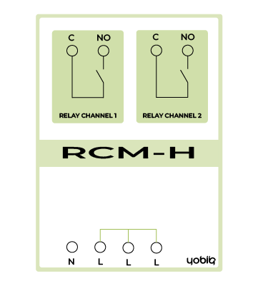
The dashed links are optional. Confirm the required connections against the approved drawing for the supplied model.
Connect the AC supply between neutral (“N”) and one of the line (“L”) terminals. The three “L” terminals are internally connected and may be used as a line connection bar where the approved model drawing permits. Use that drawing to confirm the exact connections for your installation.
DC supply (RCM-L)

A 5–24 V DC supply connects to the “+” and “−” terminals at the bottom of the device. The two “+” terminals are internally connected to each other, as are the two “−” terminals; they may be used as bus connections where the approved model drawing permits.
The RCM has an internal 0.75 A fuse to protect the device, so an additional external fuse is not required for that purpose. Protect the wiring as required by local regulations. The DC input also has reverse-polarity protection and overvoltage protection for transients up to 120 V.
Prepare the network
RCM supports LoRaWAN 1.0.4, OTAA, and Class C by default, with Class A configurable.
- Obtain the device's OTAA provisioning information and access to the intended LoRaWAN network server.
- Check gateway coverage and the regional configuration.
- Select the RCM payload decoder and command reference for the installed firmware.
Operate the device
Remote switching
Use your LoRaWAN application to request changes to the selected relay output. One-relay variants have one output; two-relay variants have two independently controlled outputs. Use the RCM command reference for the installed firmware.
Onboard schedules
The operating schedule is stored inside the RCM. Configure and verify the schedule for the connected equipment during commissioning.
Local pushbuttons
Use the pushbuttons on the device to control connected equipment locally. Follow the button assignments for the supplied variant and check the interaction with schedules and remote requests.
Configurable fallback
After power or network loss, the RCM returns to a configurable fallback state. Choose the appropriate state for the equipment, record it and verify recovery during commissioning.
Current measurement
Current measurement is available on the variants identified in the datasheet. Use the matching firmware reference for reporting and configuration.
Contact Yobiiq support with the model, SKU, hardware and firmware versions, network platform and observed behaviour.
UG-RCM · Revision 1.0 · 25 September 2026.