INSTALLATION & OPERATION
RM200User guide
Identify the device, prepare the installation, join a LoRaWAN network and understand local relay operation.
- 01 / Prepare
- Identify & install
- 02 / Connect
- Join the network
- 03 / Operate
- Control each relay
- 04 / Diagnose
- Read the indicators
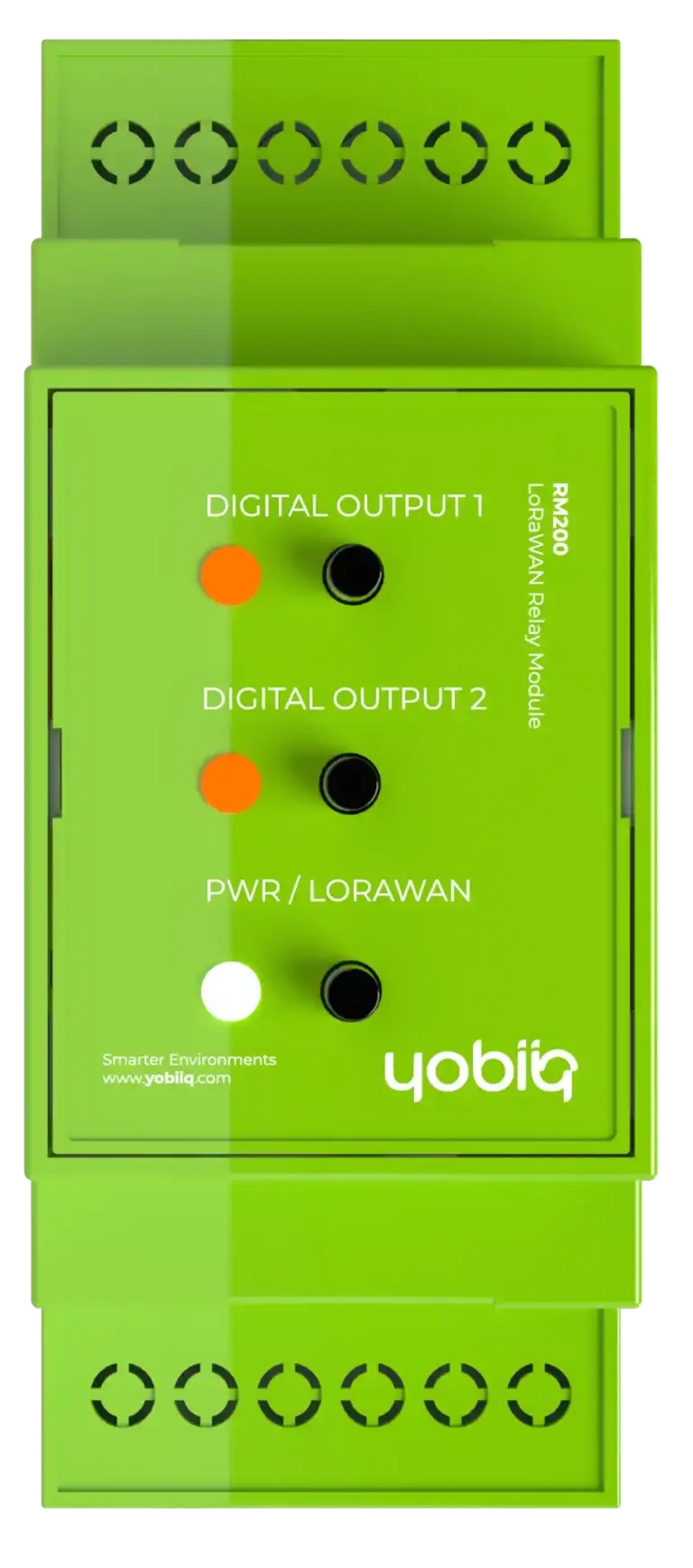
- 1Channel 1
Relay button & status LED
- 2Channel 2
Relay button & status LED
- 3Device status
Restart / join button & LED
Before you begin
This guide covers RM200 / P1002003, using the GitBook manual identified as firmware V1.1.0. Check the model, version and LoRaWAN region on the label on the side of the enclosure.
Have the matching device documentation, access to your LoRaWAN network server and the device provisioning information ready. The network needs an appropriately configured gateway and server before the device can report data or receive remote commands.
The RM200 uses mains power. Installation and maintenance must be performed by qualified personnel with the power isolated, in accordance with local electrical regulations. Check the device label and the approved connection drawing for the supplied hardware before making connections.
1. Mount & identify the connections
- With power isolated, mount the module using its built-in clips on a standard 35 mm DIN rail. The documented enclosure is 36 mm wide.
- Identify the relay connections at the top and the power-supply connections at the bottom, as described in the GitBook installation chapter.
- The chapter describes a C (common) and NO (normally open) connection for each relay. The two channels are isolated from each other and from the mains supply.
- The terminals accept 0.5–2.5 mm² conductors. Use the terminal markings and the approved wiring information for the exact unit.
The image above identifies the device and its controls; it is not a wiring diagram. A manufacturer-approved terminal drawing will be included in the final guide. Do not infer terminal numbers or wire colours from the product photograph.
Keep the device away from heat sources and damp conditions. For electrical ratings and environmental limits, use the separate datasheet.
2. Register the device & start up
Network preparation
- Match the network-server device profile to the region and LoRaWAN version shown in the device documentation. The RM200 specification lists EU 863–870 MHz and LoRaWAN 1.0.4.
- Provision the device for OTAA using the identifiers and credentials supplied for that device. The manual states that the DevEUI is printed on the device and its packaging.
- Install the matching IQ-RM200-LRW payload decoder where your platform requires one. The published application port is 50.
- After the electrical installation has been checked, apply power and observe the status LED and network-server events.
Startup sequence
The device loads its stored configuration, starts its join sequence and calibrates its connected peripherals. After a successful join, it performs a network-quality test. The manual states that sampling starts after successful calibration even if the join has not yet succeeded.
The LoRaWAN chapter describes a retry window of approximately ten minutes for devices that have not joined. Use the observed join events and LED indication to diagnose connectivity rather than repeatedly cycling the supply.
3. Operate the relay channels
Automatic control
In Normal Mode, LoRaWAN downlinks determine the requested relay state. Use the matching command specification and firmware decoder for the device; the guide does not introduce new command bytes or register addresses.
Local pushbutton control
Each channel has its own button. The physical-interface chapter describes Normal Mode, Manual On and Manual Off selections. A local override changes the channel from automatic to manual control and triggers a LoRaWAN uplink event.
| Mode | How the channel is controlled |
|---|---|
| Normal Mode | Remote relay requests over LoRaWAN |
| Manual On | Local override requests the relay on |
| Manual Off | Local override requests the relay off |
The override mode is retained across a power outage. The application-operation chapter also describes a downlink that returns a channel to Normal Mode. Internal overtemperature protection can turn the relay off even when a manual override requests it on.
Status button
| Button action | Documented function |
|---|---|
| Press for less than 2 seconds | Restart the device |
| Press for more than 5 seconds | Start the join procedure |
These durations come from the RM200 physical-interface chapter. They are not a factory-reset procedure.
4. Set restart & communication-loss behaviour
Default state after restart
On connection of mains power or a device reset, each relay uses its configured default state. The available settings are Off, On and Retain. Retain restores the last known relay state saved in flash memory.
Communication watchdog
When the LoRaWAN communication watchdog reports an outage, the requested relay state changes to the configured timeout state. The application-operation chapter lists the same three options: Off, On and Retain. The watchdog timeout is configurable.
Choose restart and communication-loss behaviour for the connected equipment during commissioning. These are separate settings; document both before handing over the installation.
Temperature protection
The RM200 monitors its internal circuit temperature. The manual states that a temperature alarm turns both relay channels off regardless of the requested or manual state. When the temperature has fallen sufficiently, the device returns to its initial state.
The exact threshold and recovery temperature need confirmation for the supplied firmware before they are added to the final parameter reference.
5. Read the LEDs
Device status
| Indication | Meaning in the RM200 manual |
|---|---|
| Alternating red / green | Device startup |
| Blinking orange | LoRaWAN join in progress |
| Blinking green | LoRaWAN uplink transmission |
| Five red blink cycles | Uplink transmission failed |
| Alternating red / orange | Network-quality test in progress |
| Steady red | Device error |
| Steady green | Device OK |
Network-quality result
| Indication | Result |
|---|---|
| Red blinking for 10 seconds | Bad |
| Orange steady for 10 seconds | Medium |
| Green steady for 10 seconds | Good |
Channel status
| Channel LED | Relay state | Control mode |
|---|---|---|
| Steady green | On | Automatic |
| Steady red | Off | Automatic |
| Alternating green / white | On | Manual |
| Alternating red / white | Off | Manual |
Use both the colour and the pattern to identify the status. The tables above describe the published RM200 manual; hardware and firmware revisions must be checked during technical review.
6. Troubleshoot & request support
| Observation | What to check |
|---|---|
| Join does not complete | Match the device identity, OTAA settings and radio region; check gateway coverage and join events in the network server. |
| Remote command does not change the output | Check whether the channel is in manual override, whether a temperature alarm is active and whether the downlink matches the device firmware. |
| Unexpected state after a restart | Review the default-state setting and the retained manual-override mode. |
| Relay changes state after loss of communication | Review the configured communication-watchdog timeout and timeout state. |
| Red device-error indicator | Record the indication and network events, then request support. |
These checks are editorial guidance based on the operating modes above. The existing GitBook troubleshooting page provides an issue-reporting checklist rather than a detailed fault-code catalogue.
When contacting support, include the model, firmware version, network platform, observed LEDs, relevant error messages and steps that reproduce the problem. Use Yobiiq contact & support.
Maintenance & document history
Maintenance must be carried out by qualified personnel with the power isolated. The current RM200 GitBook maintenance page contains no service interval or additional procedure. Those details require product-team confirmation before the final guide is released.
UG-RM200 · Revision 0.1 · 23 September 2026 · Technical review pending.
Source chapters: Introduction, Safety information, Installation, Physical interfaces, Operation, Application operation, LoRaWAN communication and Troubleshooting.